Threat Response Auto Pull (TRAP) - Installation Guide
Installation guide provides information on how to get Threat Response Auto Pull (TRAP) up and running in your environment. The Installation guide includes the list of hardware requirements, all the major steps to install Threat Response Auto Pull image in VMware environment, configure required bootstrap services, and perform initial configuration.
TRAP Installation Requirements
Virtual Machine Requirements
TRAP Auto Pull (TRAP) is a stand-alone virtual appliance. It is distributed as an OVA file, and can be downloaded from the Proofpoint Customer Portal.
The virtual machine requires the following, minimum hardware configuration for production deployments:
- 4x vCPU Cores (8x vCPU cores recommended)
- 8 GB RAM (16 GB RAM recommended)
- 50 GB HDD (base system for version 5.0 and beyond)
- 500 GB HDD (local databases and backups)
- 1 network adaptor (default is E1000 but VMXNET3 is also supported)
For administration and general usage, TRAP will need one IP address allocated to it for network access. If you plan to build a cluster for high-availability, you will need one local IP per-system, plus a single management IP to be shared between the systems.
Active Directory Requirements
Active Directory enables Threat Response Auto-Pull to gather details about users in alerts including information such as group membership, department, location, and more. Threat Response Auto-Pull requires read-only permissions in Active Directory.
Exchange Web Services Requirements
Threat Response Auto-Pull requires the connection with Exchange Web Services to perform email quarantine action. To configure Exchange EWS, you will need the following information:
- Exchange Web Services:
- EWS URL: Based on your Exchange deployment you will need the Exchange Web Services URL. If you have a hybrid Exchange setup, you can configure both Exchange on-premise and Office 365 EWS URLs.
- On-premise Exchange:
https://yourexchangehost.yourdomain.com/ews/exchange.asmx- In most cases, this host is same as the one that is hosting the Exchange OWA service.
- Office 365:
https://outlook.office365.com/ews/exchange.asmx
- On-premise Exchange:
- (Optional) EWS Certificate: If you are using a self-signed certificate on Exchange CAS server for EWS service, you will need to import the cert to TRAP certificate store.
- EWS URL: Based on your Exchange deployment you will need the Exchange Web Services URL. If you have a hybrid Exchange setup, you can configure both Exchange on-premise and Office 365 EWS URLs.
- Exchange Service Account: TRAP requires a service account with the privilege to quarantine messages in targeted mailboxes. This service account must meet the following requirements:
- The service account must have an associated mailbox
- The service account must have permission to scan targeted mailboxes. Choose one of the two supported exchange permission models:
- Application Impersonation role (recommended): Grant explicit application impersonation role to the Exchange service account used for TRAP. Please ensure that this account has no other Exchange permissions or roles assigned.
- Full Access permission: The Exchange service account used for quarantining has “Full Access” permission to all mailboxes.
- Exchange Throttle Setting: To enable faster email quarantine rates, we recommend exempting this service/user account from any EWS Throttling limitations you may have configured on Exchange CAS server.
Supported Exchange Versions
TRAP supports the following:
- Exchange on-premise: Exchange 2010, 2013, 2016, and 2019
- Office 365
Required ports for network communication
TRAP requires the following ports to be opened for management purposes, and to allow it to communicate with your devices. Refer to the table below for a list of ports that should be allowed between TRAP and other systems.
| Port | Direction | Purpose |
|---|---|---|
| TCP/8080 | Admin Network to TRAP | Appliance Management Console |
| TCP/22 | Admin Network to TRAP | SSH access to CLI |
| TCP/443 | “Any” to TRAP | TRAP GUI & HTTPS alert listeners |
| TCP/443 | TRAP to “overcast.proofpoint.com” | Communication with Overcast for Alert Enrichment |
| TCP/443 | TRAP to “overcast.proofpoint.com” | Communication with Overcast SmartSearch export from the Admin Portal |
| TCP/443 | TRAP to “tap-api-v2.proofpoint.com” | Pulling alerts from TAP |
| TCP/443 | TRAP to “saasisolation.com” and “proofpointisolation.com” | Rendering suspicious web pages from abuse-reported messages using Proofpoint Browser Isolation |
| TCP/443 | TRAP to Exchange/O365/Gmail | Used to quarantine messages |
| TCP/443 | Threat Response to login.windows.net | Used to obtain OAuth token from Azure AD Auth for O365 connectivity |
| TCP/389 | TRAP to LDAP Server | Query LDAP for user details |
| TCP/25 | TRAP to Mail Server | Notifications & alerts via email |
| UDP/53 | TRAP to DNS Server | DNS services |
| UDP/123 | TRAP to NTP Server | NTP services |
| TCP/2224 | Threat Response Clustering | Basic Clustering comms |
| UDP/5405 | Threat Response Clustering | Basic Clustering comms |
| TCP/7789 | Threat Response Clustering | Disk Replication |
Supported browsers
TRAP supports the following browsers:
| Browser | Version |
|---|---|
| Google Chrome | 51.0 + |
| Mozilla Firefox | 47.0 + |
Supported hypervisors
Today TRAP supports the following virtualization environments:
- VMware ESX/ESXi 6.0 at minimum.
Initial TRAP configuration
Building TRAP VM
Importing TRAP to VMware
This example shows how to configure the Proofpoint TRAP on VMware ESX 6.0.
Note
This example assumes you have downloaded the OVA file from the Proofpoint Customer Portal as described in your Proofpoint Welcome letter.
To install TRAP in a VMware environment:
- Start the VMware vSphere Client on your workstation.
- Log in to the VMware ESXi server that will host the VM.
-
Select
File > Deploy OVF Templateto open theDeploy OVF Templatedialog box.Note: the installation steps are listed in the panel on the left. You can use this list to follow your progress.
-
Go to the
Deploy from filefield and browse to the TRAP OVA file. - Click
Open, then clickNext. - Verify the
OVF Templatedetails then clickNext. - Review the TRAP End User License Agreement.
- Click
Accept, then clickNext. - Accept or change the default name in the
Name and Locationfield, then clickNext. - Select the resource pool for this VM, then click
Next. - Select the data store to use for the TRAP files, then click
Next. -
Map the networks in the OVF template to your networks, then click
Next.Note: The managed devices must be reachable from the TRAP virtual appliance.
-
Review the settings and click
Finishto begin installing TRAP.Note: The system takes a few minutes to import the virtual appliance. Do not shut down the application during this process.
-
In the Deployment Completed Successfully window, click
Close.
Initial Configuration Wizard (New)
Once you deploy the Threat Response VM, you can proceed with the initial configuration. Begin by powering up Threat Response.
- In the vSphere Client, select the Threat Response appliance that was just installed. Right-click the name, then click on
Power > Power On. - Launch a
Consolefor this VM. - Go to the next section to begin configuring the Threat Response appliance.
Once Threat Response has started, you can proceed with the Initial Configuration Wizard. This can take up to five minutes.
-
Open a console window to start the Initial Configuration Wizard.
-
Type
adminat the prompt, then pressEnter. -
Set an administrator password for your admin user.
-
Enter the password again for verification purposes.
-
Enter (set) a hostname for the appliance. Be sure to record it in the Managing TRAP Configuration Information section below.
-
a. (Optional) Select
yesforDHCP, then pressEnterif you want to use aDHCPserver to dynamically assign an IP address to Threat Response.
b. Select no for manual configuration by means of three prompts:
-
Enter an IP address and netmask in the Classless Inter-Domain Routing (CIDR) format (IP address/masking bits), e.g. 10.21.68.21/8.
-
Enter your gateway IP address.
-
List any DNS servers separated by commas.
Note that new first boot steps have been added to version 5.0.1 (and beyond).
Threat Response uses the following two gateways/subnets for internal use by default:
- 172.31.250.1/24 is a subnet used by Docker containers running various back-end services in Threat Response.
- 172.31.251.1/24 is a subnet used by Docker containers created for scripted listeners, pollers, and responses.
Importantly, if they conflict with your network, you will not get return network traffic to any addresses within those ranges. If you choose Yes (to change the gateways), the following will appear. Note that the gateways must be different, unique subnets. Moreover, they are only meant to be routed within the appliance.
- Enter the gateway/subnet in CIDR format for Threat Response services, e.g. 172.31.250.1/24.
- Enter the gateway/subnet in CIDR format for Threat Response scripting services, e.g. 172.31.251.1/24.
You will be asked if you want to confirm the entirety of the settings above. Choose Yes to configure and initialize the system. This may take a few minutes.
Note
Importantly, these two /24 subnets have not been extracted from the existing network infrastructure. Note that you may pick two IP address ranges that do not overlap with anything else in your data center. Alternatively, you can pick Class C network IP address ranges (192.x.x.x).
Initial Configuration Wizard (Old)
Once you deploy the TRAP VM, you can proceed with the initial configuration. Begin by powering up TRAP.
- In the vSphere Client, select the TRAP appliance that was just installed. Right-click the name, then click on
Power > Power On. - Click the
Consoletab to emulate a console port. - Go to the next section to begin configuring the TRAP appliance.
Once TRAP has started, you can proceed with the Initial Configuration Wizard. This can take up to five minutes.
- Open a console window to start the Initial Configuration Wizard.
-
Type
adminat the prompt, then pressEnter. Further, if the system prompts you for a password, enter proofpoint. -
Type
yesat the “Do you want to use the wizard …” prompt, then pressEnter. -
Enter (set) a
namefor the virtual machine at theHostnameprompt, then pressEnter. Be sure to record it in the Managing TRAP Configuration Information section below. -
(Optional) Select
yesforDHCP, then pressEnterif you want to use aDHCPserver to dynamically assign an IP address to TRAP. - Enter your choice of a password at the
passwordprompt, then press Enter. Be sure to record it in the Managing TRAP Configuration Information section below. -
Reenter your password when prompted, then press
Enterto save your changes and to exit the program. Note that when you enter and reenter your password, no keystrokes are displayed on the console; however, the password is being entered. -
Enter your admin email address, then press
Enter. -
Scroll through the list of available time zones to find your applicable code. Enter
n(for “next”), then pressEnterto scroll through the next series orp(for “preceding”), then pressEnterto scroll through the preceding series. Codes applicable to the mainland United States time zones areUS/Eastern: 509 US/Central: 507 US/Mountain: 513 US/Pacific: 514 -
Enter either the text string or the numeric value for the time zone, then press
Enter. - Enter your
NTP server nameat the NTP server prompt if you want to use such a server or enterNoif you do not, then pressEnter. - Review your information. To change an answer, enter the relevant step number, then press
Enter. To proceed, pressEnterto save any changes and to exit the Wizard.
Determining the DHCP Address
Use the steps below to display the system’s IP address if DHCP was selected during the “initial configuration” discussed above.
- Log in to the Threat Response/TRAP console.
- Enter
enableat thehostnameprompt, then pressEnter. - Enter
show interfaces eth0at the hostname# prompt, pressEnter. - Record the IP address in the Managing TRAP Configuration Information section below because it is not possible to copy and paste it from the console script window.
- Type Exit to log out of the console.
Managing TRAP Configuration Information
This section provides an opportunity to manage important TRAP configuration information efficiently.
| Gather the following information | Record the information here |
|---|---|
| Hostname | |
| VM Username | |
| VM Password | |
| TRAP IP Address | |
| Hostname of Virtual Machine |
License Installation
Use the steps in this section to install the TRAP License.
- Open the Proofpoint Welcome email containing your license.
- Locate and copy the license key to use in step 7 below.
- In the browser window, enter
https://ptr_ip_address:8080. -
Provide the Proofpoint
usernameandpasswordthen pressEnterto open the Proofpoint Appliance Management Console window.Use the IP address assigned to the TRAP virtual machine in the Deploying the Virtual Machine section earlier in this chapter or go to the Managing TRAP Configuration Information section if you recorded the IP address there.
-
Click the
Setuptab then clickLicensingin the left menu. - Paste the Proofpoint license key you copied from the Proofpoint Welcome email (in step 2 above) into the text field below Add New License.
- Click Add Licenses then click Save in the top right corner of the window to validate and save the license.
Note
TRAP licenses have expiration dates. A month before your license expires, TR opens a pop-up message each time you log in reminding that your license will expire soon. Once it expires, you will not be able to log in until you enter a new license in the Proofpoint Appliance Management console window. To renew your license, contact Sales at 1-877-634-7660.
Logging Into TRAP
Use the steps in this section to run TRAP in a browser window.
- Open a supported browser.
-
Navigate to
https://ptr_ip_addressto open the Proofpoint TRAP login window.This is the IP address assigned to the TRAP virtual machine when you set up your virtual environment in the Deploying the Virtual Machine section of the previous chapter.
-
Enter your
usernameandpasswordinto TRAP login window.This is the admin password you created for yourself when you set up the virtual machine in the Deploying the Virtual Machine section and recorded in the section, Managing TRAP Configuration Information.
-
Click
Loginto open the TRAP Dashboard window. Initially, this window will be empty of data.
Active Directory and LDAP
LDAP / Active Directory support enables TRAP to map users to alerts that it receives, and to retrieve details about user accounts, such as location and group membership. The configuration is broken up into the two sections below.
Server Configuration
Create a server listing in TRAP to tell the systems which LDAP server to query for user information. Multiple servers can be created.
- Log in to TRAP.
- Navigate to
System Settings>Contextual Data Sources>LDAP Servers. - Click the blue Add (+) button next to LDAP Servers to bring up the New LDAP Server panel.
- Set the following fields:
- IP/Hostname:
<ldap_hostname_or_ip> - Port:
<ldap_port> - SSL: Check to enable SSL encryption
- Search Base:
<directory_path>(e.g., DC=domain,DC=com) - Requires Authentication (Optional)
- IP/Hostname:
- Save changes.
Note
The authentication username may vary in syntax depending on your directory server’s authentication requirements. In most cases, the full, distinguished name (DN) for the user should be used as the username.
LDAP attribute selection
TRAP allows you to configure the user attributes that will be pulled from your LDAP / Active Directory server. By default, the system is configured to collect and display the following common user attributes:
- Display Name
- Telephone Number
- Mobile Number
- Email Address
- Company
- Department
- Street Address
- City
- State
- Country
- Group Memberships
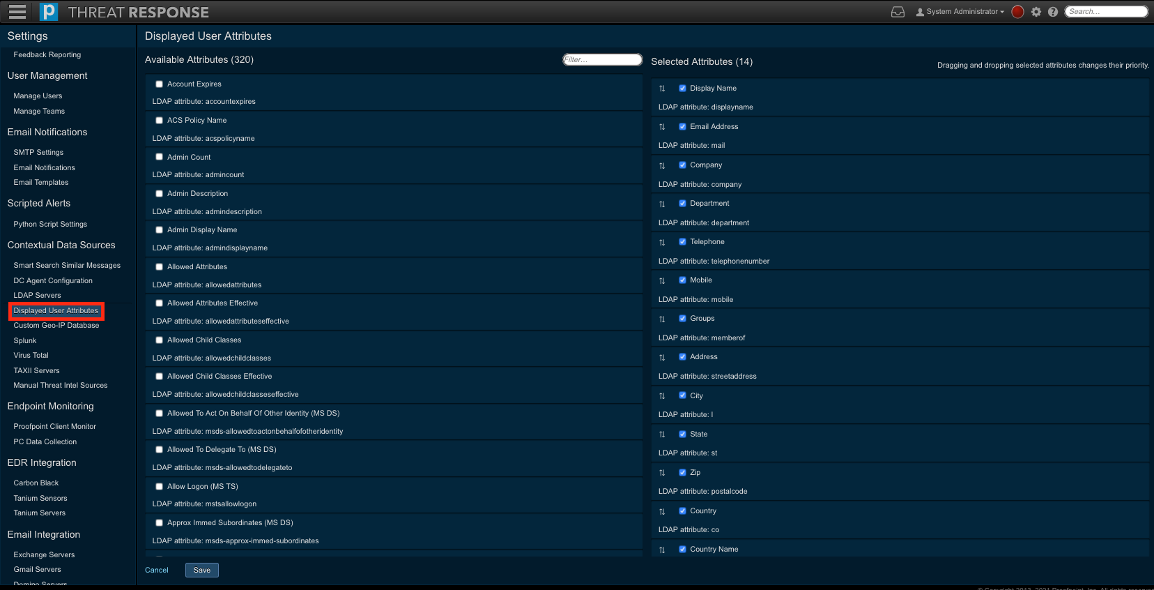
To add, or remove items from this list, use the steps below.
- Log in to TRAP.
- Navigate to
Settings>Contextual Data Sources>Displayed User Attributes. - Select attribute that you would like to be displayed for users.
- Place a checkmark next to items in
Available Attributesto select them - Uncheck items in Selected Attributes to remove them
- Place a checkmark next to items in
- Re-order the Selected Attributes by dragging-and-dropping items into your preferred order. This is how they will be displayed in the UI.
- Click
Save.